

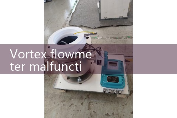
『Vortex flowmeter malfunction』Related information(clamp on meter|electromagnetic meter|venturi meterrotameter|orifice meter|ultrasonic flow meter|mass flow meter|coriolis mass flow meter|coriolis flow meter|magnetic flow meter|magmeter flow meter|magflow flow meter|mag meter flow meter|electromagnetic flow meter|vortex flow meter|turbine flow meter|thermal mass flow meter|thermal flow meter|rotameter flow meter)
1. What should I do if the vortex flowmeter does not count and the signal has no output?
When the vortex flowmeter of Xuner Instrument shows the situation of "no data displayed, no signal output", the following steps can be taken to troubleshoot and handle it:
1. Check the instrument itself and check the settings: First, check the instruction manual to confirm whether the instrument settings are correct, to avoid no signal output caused by incorrect parameter settings.
. Tap test: Use a hard object to tap the vortex flowmeter and observe if there is any flow display. If there is a flow display, it may be due to the absence of medium flow in the pipeline, cracking and seepage, or the medium flow rate not reaching the lower limit of the vortex diameter. At this point, it is necessary to check the condition of the pipeline medium to ensure that the medium flows normally and the flow rate is within the measurement range of the instrument. If there is no traffic display: proceed to the next check. Sensor lead testing: Remove the sensor leads from the circuit compartment on the amplification board, then short-circuit the sensor lead terminals on the amplification board and touch them with your hand. If 50 or 100Hz is displayed, it indicates that there is a problem with the sensor and it may need to be replaced. If there is no display: it indicates that there is a problem with the amplification circuit, and the amplification circuit needs to be repaired or the relevant circuit components need to be replaced.Secondly, investigate the on-site situation of the instrument and common ground problems. If the instrument itself has no problems, it is necessary to consider the situation where the instrument
2. What are the common faults of vortex flowmeter? How to solve it?
3. What are the emergency handling methods for the display of over range in vortex flowmeters?
The core principle for emergency handling of over range display in vortex flowmeters is to quickly restore the normal operation of the process first, and then investigate the cause of the over range, which can be promoted in two directions: temporary emergency and long-term investigation. Temporary emergency handling steps 1 First time load reduction or medium cut-off: If the fluid flow rate instantly exceeds the upper limit of the range, immediately reduce the fluid flow rate and flow rate in the process pipeline, or close the upstream and downstream valves to cut off the medium, to avoid con
 Hot Blog
 Related AD